Power converters can provide support to the grid during short-circuit faults. This blog reviews the traditional fault current calculations to take into account converters support when solving unbalanced short-circuit faults. In addition, some current injection control strategies are studied and compared.
Introduction
Of all the events that an electrical grid can undergo, short-circuits are highly unavoidable and can be very severe. Therefore, the grid must be ready to deal with them. That is why it is crucial to know how to calculate accurate short-circuit fault currents: to ensure a proper grid design and operation.
In modern days, power converters are required to support the grid during short-circuit faults to keep the voltage values as close as possible to pre-fault values. Therefore, their presence and contribution must be considered when calculating short-circuit fault currents.
Formulation
Traditionally, the short-circuit fault currents calculations in sequence components do not contemplate the presence of active elements (i.e., voltage or current sources) in any sequence other than the positive sequence. This changes when power converters appear, as they offer to inject current in the negative sequence.
For instance, the proposed sequence fault currents for a line-to-line fault end up being:
$$ \underline{I}^0_f = 0, $$
$$ \underline{I}^+_f = \dfrac{\underline{V}^+_{th,q} - \underline{V}^-_{th,q}}{\underline{Z}^+_{qq} + \underline{Z}^-_{qq} + \underline{Z}_f}, $$
$$ \underline{I}^-_f = - \underline{I}^+_f. $$
where $$\underline{I}^{0}_{f}$$, $$\underline{I}^+_f$$, $$\underline{I}^-_f$$ are the direct, positive and negative sequence fault currents, respectively, and $$\underline{Z}^i_{qq}$$ , $$\underline{V}^i_{th,q}$$ the grid Thévenin impedance and voltage equivalents of sequence $$i$$ as seen from faulted bus $$q$$.
Once the fault currents are obtained, the voltages of the system can be calculated by superposition, as done traditionally in literature. However, it is at this point that the problem gets more complex.
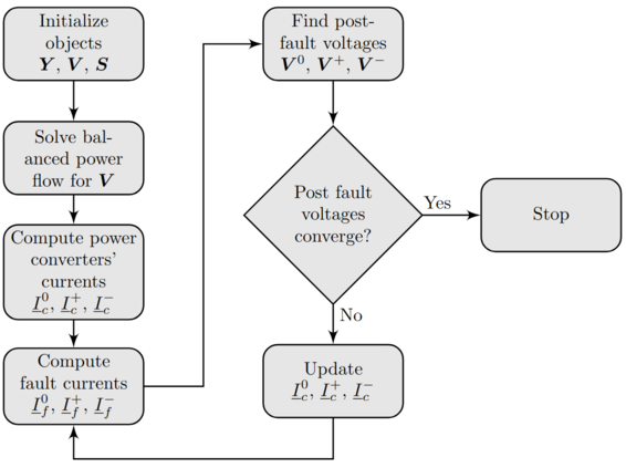
If we consider that the converters can inject a variable current depending on the voltage at the bus they are connected to, it is clear to see that new converters’ current injection must be calculated as well as new fault currents and new short-circuit voltages. Hence, an iteration, similar to the one proposed here must be defined, as seen in Figure 1.
 Figure 1: Algorithm to solve short-circuits including power converters’ contribution.
To compute the power converters’ injection currents we have compared different strategies, in order to see which ones obtain the best results for the grid. The proposed current injection strategies are the following:
- MP : inject the maximum current permitted by the converter on the positive sequence.
- MN : inject the maximum current permitted by the converter on the negative sequence.
- PD : follow the grid codes for the positive sequence droop.
- ND : follow the grid codes for the negative sequence droop.
- GCP : the application of the positive sequence droop and injection of the remaining current capability in the negative sequence.
- GCN : the application of the negative sequence droop and injection of the remaining current capability in the positive sequence.
- OPMX : solution of an optimization problem to maximize the positive sequence voltage.
Results
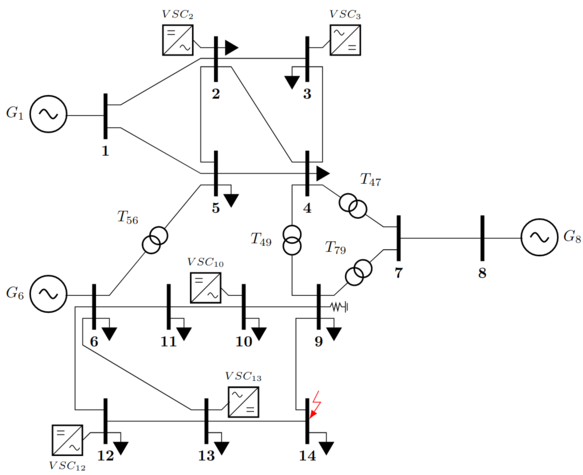
We have tested several grids with an increasing power converters’ penetration. For example, IEEE 14-bus grid modified as seen in Figure 2. The 5 added converters can inject 25% of the demanded power in total, to simulate a 25% of renewable energies penetration.
 Figure 2: Modified IEEE 14-bus grid.
For a line-to-line short-circuit fault simulated at bus 14, the results in p.u. are shown below.
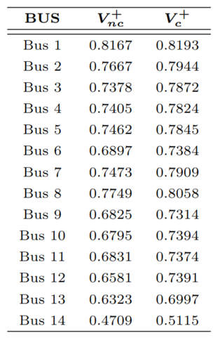
To begin with, it is important to verify that the converters help the grid. In Table 1 it is clear that the short-circuit voltages are higher thanks to the presence of power converters, $$V_{nc}$$.

Table 1: Line-to-line fault results for OPMX strategy with $$V_c$$ and without $$V_{nc}$$ converters.
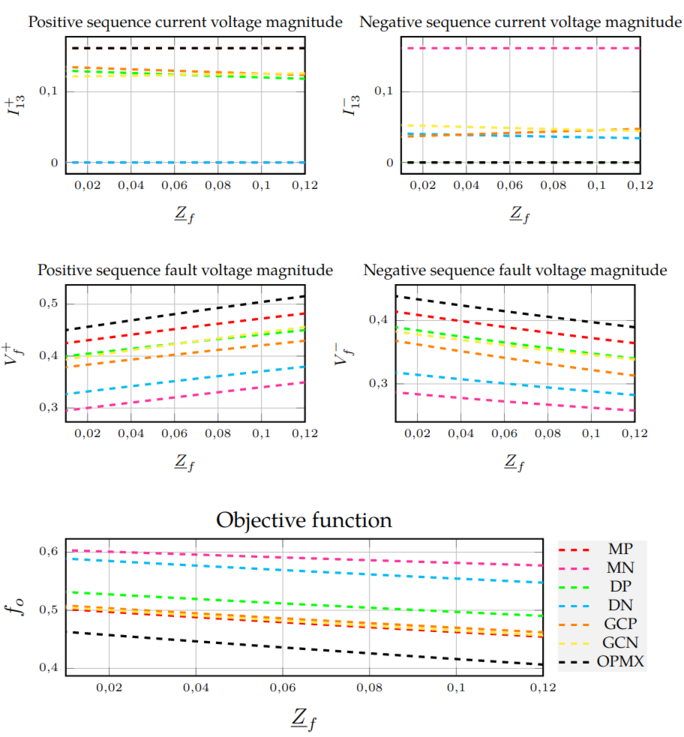
Then , the graphical results for different variables are found in Figure 3.
 Figure 3: Line-to-line fault results for modified IEEE 14-bus grid.
Note that the objective function $$f_o$$ is defined as the mean of the difference between the balanced voltages and the postfault voltages:
$$ f_o = \dfrac{\sum_{i=0}^{m}\left({|1-V^+_i|} + {|0-V^-_i|}+{|0-V^0_i|}\right)}{m} $$
Conclusion
Power converters are shown to help the grid during short-circuit faults. The way we implement their control strategies influences the final results on the grid, therefore, it is interesting to find the best control strategy for each case. In addition, it is crucial to accurately take into account their behavior, as it is proven that results greatly vary between a grid without converters and the same grid with them.
Do not hesitate to ask if you are interested in a more exhaustive explanation!
