Power converters exhibit different behaviors when short-circuit faults arise. This blog explores the grid-support provided by converters during unbalanced faults and suggests strategies to improve it. These alternatives have been shown to yield near-optimal solutions, which supposes a substantial improvement compared to the response of traditional grid codes.
Introduction
Short-circuit faults are unfortunate events that compromise the integrity of power networks. While synchronous generators can inject currents larger than the nominal value, power converters have to carefully limit the current so as to not damage the equipment. In addition to being subjected to a maximum current, converters also have to contribute to improve the voltages during the fault, as specified in grid codes.
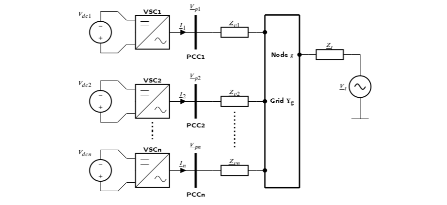
 Figure 1: Overview of a grid with power converters connected to it.
Formulation
In an ideal world, converters could an infinitely large current so as to restore the voltages to the desired values. However, in reality, converters have an inherent current limitation denoted as $$I_\text{max}$$. Disregarding the zero sequence voltage in a three-wire configuration, an optimal situation in terms of voltage support appears when:
- The positive sequence voltage magnitude $$V^+$$ approaches 1 (i.e. the nominal voltage).
- The negative sequence voltage magnitude $$V^-$$ approaches 0 and hence there are no unbalances.
The optimization problem for $$n$$ converters could then be written as:
$$\min_{\boldsymbol{I_1},...,\boldsymbol{I_n} \in \boldsymbol{I}} \quad f_o = \sum_{k=1}^n |(1 - V^+_{k})| + |(0-V^-_k)| $$
$$\text{s.t.} \quad \quad \quad \quad \quad \max(I_k^a, I_k^b, I_k^c) \leq I_{\text{max},k} \forall k \in [1,...,n]$$
where the currents of the form $$I_k^a$$, $$I_k^b$$ and $$I_k^c$$ are the phase currents injected by converters, and none of them can surpass the maximum.
Now, do we solve optimization problems such as this one in reality? Absolutely not. Grid codes specify simple rules to support faults, even though they can be far away from the optimal. It is common to inject a current proportional to the voltage variation.
- In the positive sequence:
$$I^+_{k} = k_p ( V_h - V^+_k)$$
where $$k_p$$ is a droop constant and $$V_h$$ is an upper voltage threshold of for instance 0.9 pu.
- In the negative sequence:
$$I^-_{k} = k_n (V^-_k - V_l)$$
where $$k_n$$ is a droop constant and $$V_l$$ is a lower voltage threshold of for instance 0.1 pu.
In case any of the currents above exceeds the maximum, they have to be saturated to $$I_{\text{max},k}$$. However, note that the equations above cannot be applied simultaneously. Otherwise we run the risk of exceeding the maximum current of the converter.
Our work puts to test the following control strategies:
- OPT: the solution to the optimization problem.
- GCP: the application of the positive sequence droop and injection of the remaining current capability in the negative sequence.
- GCN: the application of the negative sequence droop and injection of the remaining current capability in the positive sequence.
- GC: the application of simply the positive sequence droop.
The strategies GCP and GCN are contributions of this work as they determine the current margin in the non-prioritized sequence to not exceed $$I_{\text{max},k}$$ for any converter $$k$$.
Results
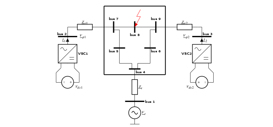
We have obtained results for balanced and unbalanced faults, for systems with one and two converters. In the case of the two-converter system, we have opted for a modified IEEE 9-bus system.
 Figure 2: IEEE 9-bus system with two converters.
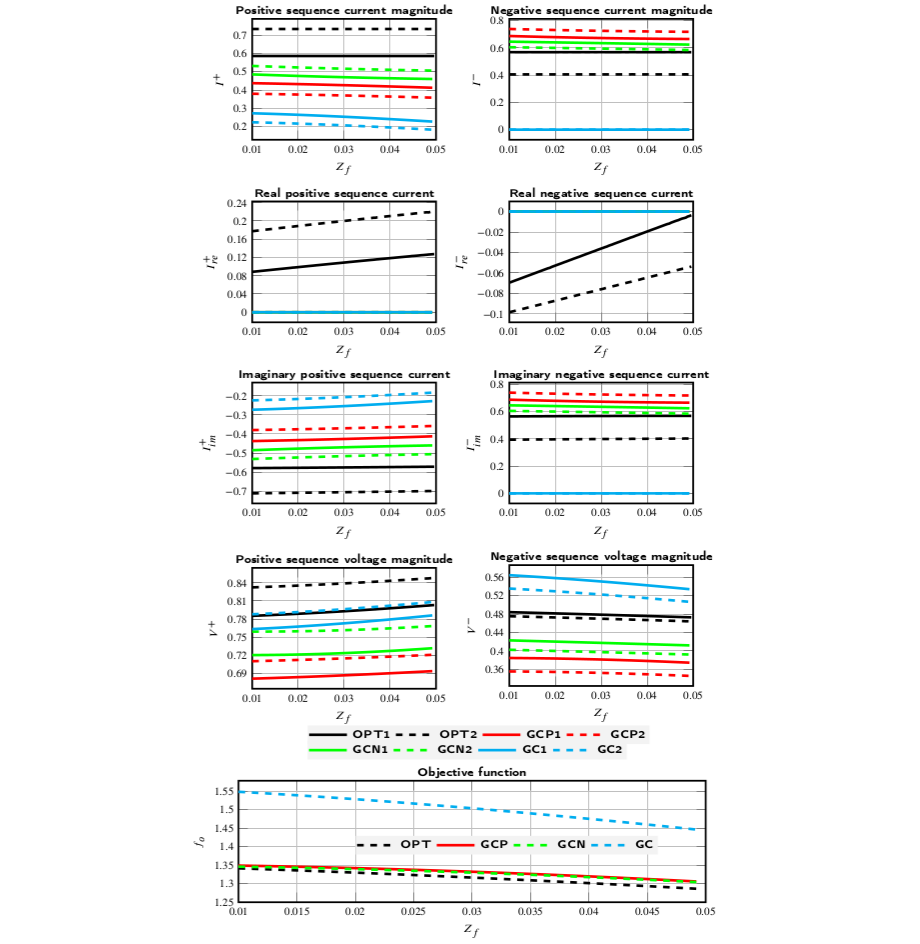
A fault impedance sweep at bus 8 has been simulated for a line-to-line fault, thus provoking an unbalance. The goal is to check if the proposed strategies GCP and GCN are close to the optimal OPT, and also understand if this supposes an improvement compared to the traditional grid code GC.
 Figure 2: IEEE 9-bus line-to-line fault results.
Note that the values of the optimization function $$f_o$$ GCP and GCN are very close to the optimal OPT. Thus, we can say that these proposed strategies are near-optimal. On the other hand, the traditional grid code GC is considerably worse. The results shown above have been dynamically validated to ensure their correctness.
Conclusion
Power converters have to collaborate at improving the voltages during faults, yet they have limited capabilities due to their current limits. Determining the currents to be injected becomes a challenge as it has to be seen how to distribute the currents between the positive and the negative sequence. Our work proposes two grid code adaptations and compares them to the optimal solution and a traditional grid code. It has been shown that these grid code adaptations are almost optimal yet they follow simple rules.
Eager to learn more? Then make sure to check our paper.
