Three-Phase Unbalanced Power Flow and Phase-Domain Short-Circuit Studies in VeraGrid
February 17, 2026
The current version of VeraGrid includes three-phase unbalanced power flow and phase-domain short-circuit analysis. The implementation is intended for networks where phase asymmetry is structurally important and where positive-sequence formulations are no longer sufficient to represent the study case with the required fidelity.
This applies especially to distribution systems, but also to any part of the grid where the electrical behavior is shaped by mixed phase availability, single-phase and two-phase laterals, asymmetrical conductor arrangements, grounded and floating neutrals, or phase-specific load and fault behavior.
Why This Was Implemented
In balanced transmission studies, a positive-sequence model is often an efficient and appropriate abstraction for power flow. In many feeder-level studies, that abstraction starts to lose important information. In addition, with the most common faults being unbalanced, short-circuit studies even at the transmission level need to consider the effects of unbalanced voltages on the network.
The issue is not only that the loading is unbalanced. The network itself is often unbalanced in structure. Lines may exist on phases a-b-c, a-c, b-c, or a alone. Loads may be connected in grounded wye, ungrounded or grounded delta, or phase-to-neutral. Capacitor banks, transformers, and distributed resources may also be connected asymmetrically. Once these features become relevant, the study is no longer well described by a positive-sequence-only formulation. For these cases, the solver needs to operate directly in the phase domain.
Modelling Basis
The implementation in VeraGrid is based on an abc phase-coordinate formulation for steady-state power flow. The same modelling basis is then extended to short-circuit studies, so the fault analysis remains consistent with the power flow method.
This design choice is deliberate. Instead of representing asymmetry through sequence networks and coordinate transformations, VeraGrid models the physical phases directly. That matters because sequence-based methods are built around assumptions that become weaker as the network becomes more heterogeneous, especially in feeders with missing phases, mixed connections, strong neutral participation, or non-trivial grounding paths.
A full phase-domain representation keeps the model closer to the physical network. It preserves the actual phase connectivity of branches and devices, and it returns phase voltages and phase currents directly, without relying on simplified reconstruction from transformed coordinates.
What Is Included
The current implementation adds to VeraGrid's existing power flow capabilities:
- three-phase unbalanced power flow in phase coordinates
- support for three-phase, two-phase, and single-phase topologies
- support for wye and delta connections
- phase-domain short-circuit calculations for balanced and unbalanced faults
- 4-wire modelling, including explicit neutral conductor representation
The 4-wire extension is particularly relevant in low-voltage and distribution studies. Lines, transformers, loads, shunts, and generators have been updated to support neutral conductor behaviour, including grounded, neutral-connected, and floating-neutral cases.
Numerical Solution Approach
The unbalanced power flow is solved iteratively using a Newton-Raphson framework adapted to the phase-domain problem. Conceptually, the method follows the same logic as a conventional steady-state load flow, but applied directly to the phases that physically exist in the network.
A key point is that VeraGrid does not assume that every bus contains all three phases. The solver identifies the active phases from the branches and transformers, then constructs a phase mask that removes non-existent phase entries consistently from the admittance matrix and from the corresponding voltage, current, and power vectors. This allows the numerical problem to be built around the actual feeder topology, including mixed three-phase, two-phase, and single-phase sections.
From there, the solution proceeds in the usual way: network interconnections are represented through the phase-domain admittance matrix, bus injections are defined through specified power, current, or admittance terms, slack, PQ, and PV conditions are imposed according to bus type, and the mismatch between specified and calculated injections is driven to zero iteratively.
Short-Circuit Formulation
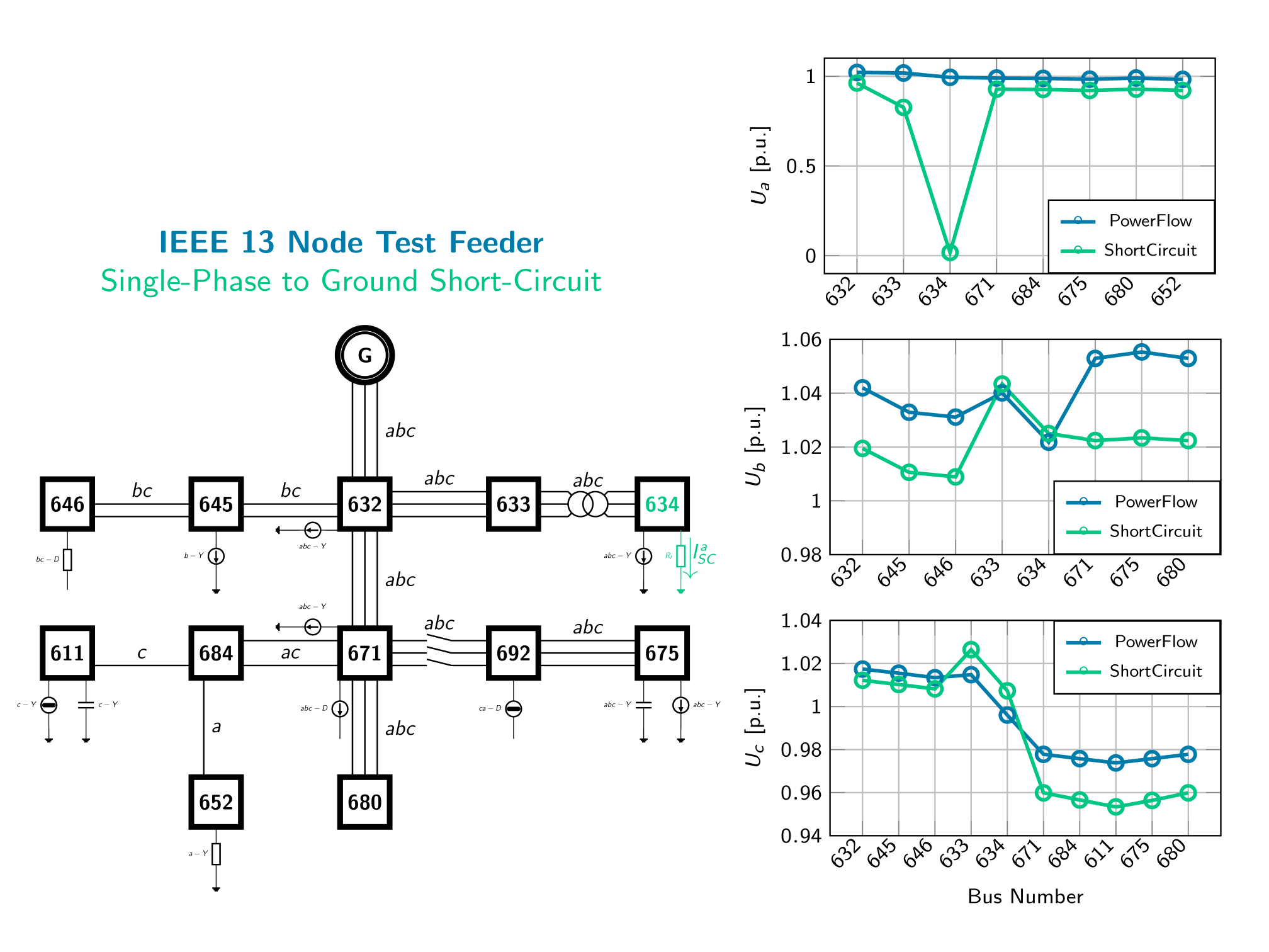
The short-circuit implementation uses the same phase-domain representation to simulate balanced and unbalanced faults directly. This is useful because many practical protection and equipment questions depend on the actual phase quantities during the fault.
Positive- and negative-sequence-based methods may be sufficient for many screening calculations, but they can hide details that matter in feeders with asymmetrical connections, non-trivial grounding paths, or strong neutral participation. A phase-domain approach allows direct observation of phase voltage collapse at the faulted location, current redistribution across phases, neutral-related behavior, and local voltage depression patterns across the feeder.
This is especially relevant for single-line-to-ground and other asymmetrical faults.
Benchmarks and Validation
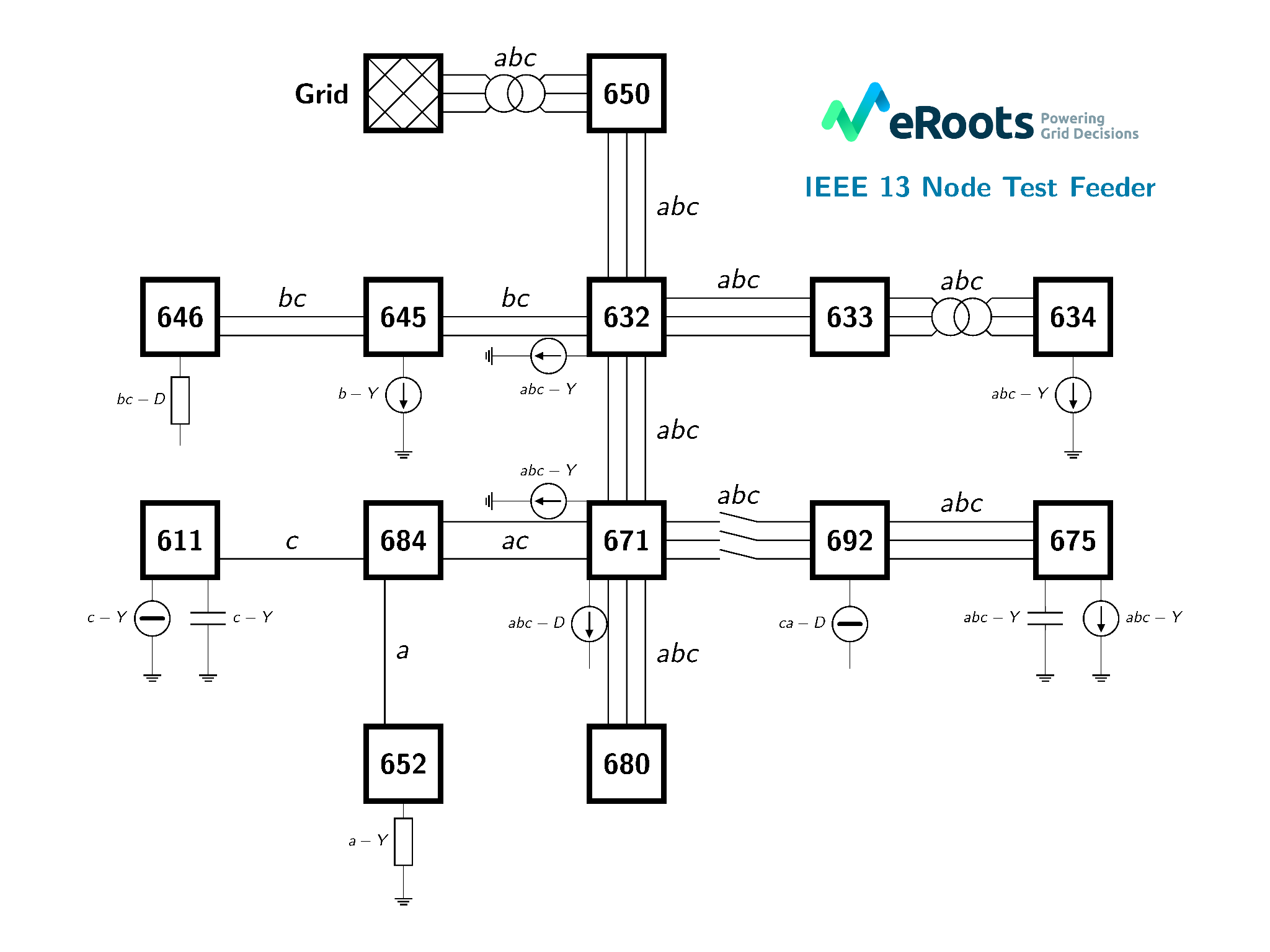
The implementation has been validated against established reference cases, including the IEEE 13-Node Test Feeder and the IEEE European LV Test Feeder with 906 buses.

The IEEE 13-node feeder is a useful benchmark because it combines several of the modelling features that make unbalanced analysis non-trivial: mixed three-phase, two-phase, and single-phase lines, grounded-wye and delta-connected loads, constant power, current, and impedance representations, shunt compensation, transformer coupling between voltage levels, and strong asymmetry across phases.
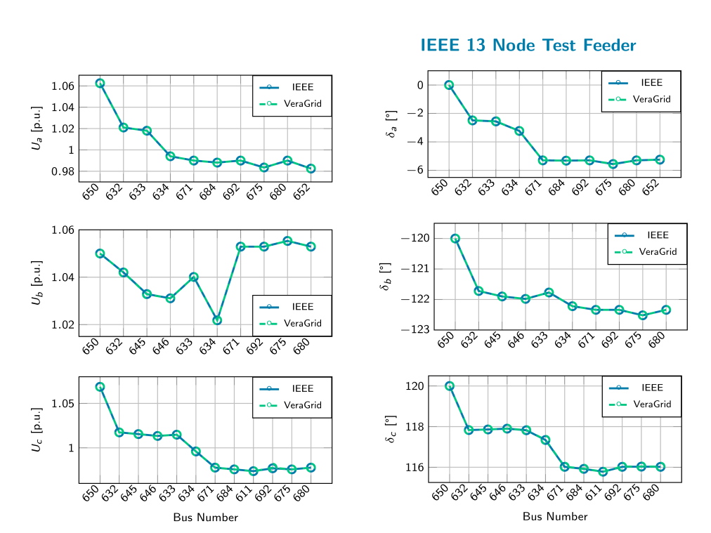
In the VeraGrid results, the phase-by-phase voltage magnitudes and angles align closely with the IEEE reference values across the benchmark buses. The short-circuit example on the same feeder also reproduces the expected phase-specific behavior during a single-phase-to-ground fault, including the collapse of the faulted phase voltage and the corresponding redistribution in the healthy phases.
Validation has also been carried out against external references and tools including OpenDSS, MATLAB Simulink, and GridLAB-D. In addition, the 4-wire implementation has been applied to real distribution networks where a large share of single-phase load is connected through the neutral conductor, precisely the type of case where explicit neutral modelling has a material effect on the solution.
How To Use It
The feature is already included in the current version of VeraGrid.
In the GUI, select the unbalanced formulation option when configuring the study.
In scripts, call the three-phase power flow solver instead of the positive-sequence solver.
The IEEE 13-node feeder example can be modelled directly in VeraGrid using the documented API structure for buses, line templates, transformers, loads, shunts, and the final three-phase power flow call.
What This Enables Next
This implementation provides the basis for a broader set of network studies where phase-domain behaviour matters. The next logical extension is toward modern AC/DC grids with converter-based resources, including current-limited fault response, phase-wise saturation, and control-dependent behaviour under symmetrical and asymmetrical disturbances.
Download and Try It
These capabilities are available in the current version of VeraGrid. If you want to test unbalanced power flow, phase-domain short-circuit calculations, or 4-wire feeder models, you can download VeraGrid and run the new formulation directly.