The unified power flow converter (UPQC) is a power electronics-based device used to improve power quality in electrical grids. At eRoots Analytics and in collaboration with TeknoCEA we analyzed a low cost design method for this type of converter.
Introduction
A high penetration of solar in the power system can cause issues with the grid voltages, particularly overvoltages and voltage imbalances. These issues can cause breakdown of the insulation of the power lines over time if not rectified and even in more minor cases decrease the efficiency of the system. The application of unified power quality converters in the grid has been investigated in academia extensively over the past few years due to their extra functionality and rapid response. However, due to the large cost of extra componenets, they are not yet viable to be implemented in power grids. However, with some functionality removed, the rating of the converter and by extension the cost can be significantly reduced. Thus, the UPQC becomes much more commercially viable.
Formulation
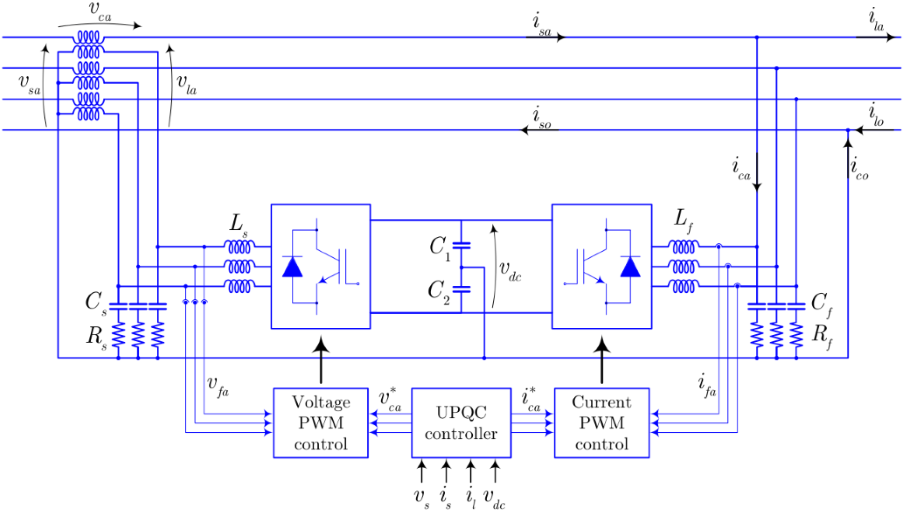
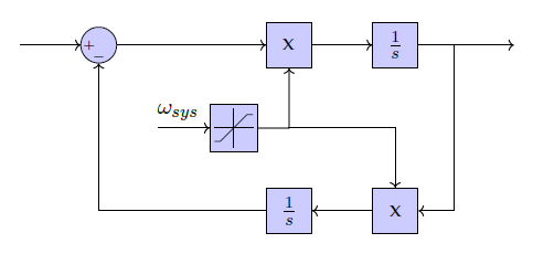
This design method is based on a static representation of the UPQC behaviour. This static representation was compared to a dyanamic model which had for control objective to correct the consumer side voltage to 1 p.u. up to a certain limit voltage. The voltages are controlled individually in each phase from the series connected side of the UPQC. This control is based off of a proportional resonant controller with a second order generalized integrator. On the shunt side of the UPQC, the controller serves to keep the DC link voltage stable while injecting minimum reactive power.
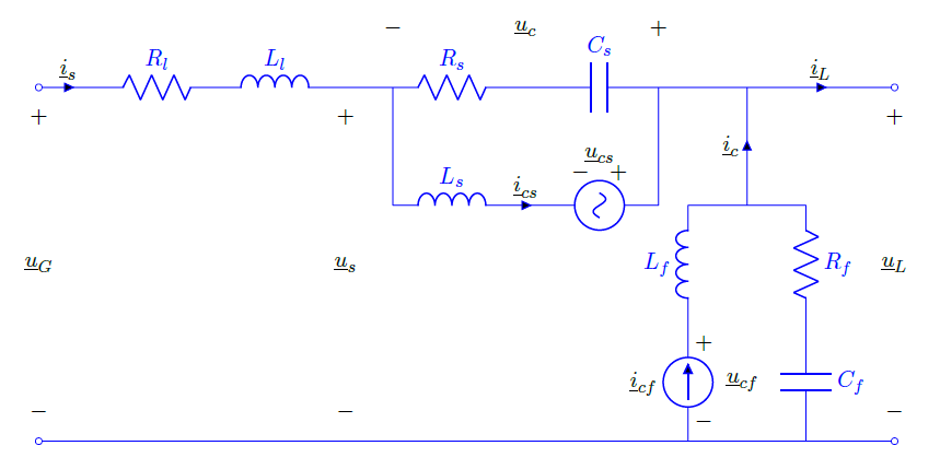
The static model itself was based off of the circuit equations, a DC link condition, and assumptions that the grid side voltage and the load side power were known. For the three static phase model, all three phases were treated independently except for the DC link condition, in which power was divided between all three phases evenly as in the dynamic model. Using these conditions, the static model managed to replicate the results of the dynamic model with a maximum error of 1% while providing a nearly instantaneous conversion time.
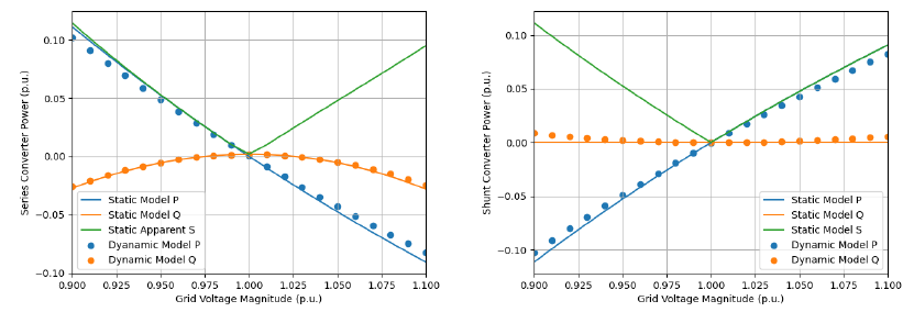
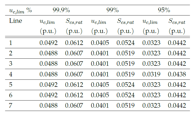
With the static model, a sizing for the transformer turns ratio can be chosen by checking when the extra apparent power from adding a turn becomes negligible. The sizing of each of the UPQC converters may then be obtained for a given maximum voltage correction.
Results
As can be seen in Figure 6, the higher the percentage of voltage deviations covered by the converter the higher the rating required by the converter to cover this correction. As such, an analysis of costs and benefits of correcting the voltage deviations can be completed by the designer to choose the optimal voltage correction limit.
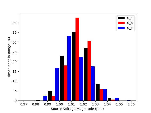
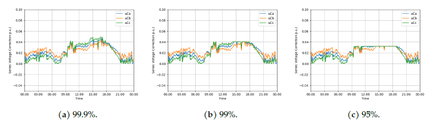
Additionally, the designer will be able to view any of the static model variables on different days or weeks to give a clearer vision of the converter response to the behaviour of power grid. For example, the voltage correction on a sample day can be observed in Figure 7.
Conclusion
With installed variable renewable generation rising across the globe, there is a need to prepare grids to face the challenges of variable generation. At eRoots Analytics, we use tools such as static representations to aid companies in making accurate and informed design decisions while working towards this goal.
Do not hesitate to ask if you are interested in a more exhaustive explanation.